Harley-Davidson Wiring Diagrams Explained – Full Guide
Harley-Davidson Wiring Diagrams Explained turns complex electrical maps into simple, readable guides. You’ll learn wire colors, symbols, and how to trace faults step by step. This resource makes motorcycle wiring repairs safe and fast for any rider.
If you own a Harley-Davidson, you know that every wire matters. Harley-Davidson Wiring Diagrams Explained is your go-to resource for understanding the electrical heart of your bike. This guide breaks down wiring schematics, symbols, and color codes into simple, easy-to-follow steps. You’ll learn how to read diagrams, troubleshoot common issues, and keep your ride running smoothly. Whether you’re a weekend mechanic or a curious rider, this full guide gives you the confidence to tackle any wiring project.
Understanding your Harley’s electrical system doesn’t have to be scary. A wiring diagram is simply a map that shows how every wire connects. It tells you where power comes from, how switches control circuits, and where grounds are made. With the right diagram, you can fix a blown fuse, trace a short, or add new accessories without guessing.
This guide will walk you through everything you need to know. We’ll cover symbols, colors, components, and step-by-step troubleshooting. By the end, you’ll feel comfortable reading any Harley-Davidson wiring diagram. Let’s dive in.
Key Takeaways
- Wiring diagrams are maps: They show every connection in your Harley’s electrical system.
- Colors and symbols matter: Each wire color and symbol has a specific meaning you must learn.
- Troubleshooting becomes easy: A diagram helps you find faults fast, saving time and money.
- Official sources are best: Use factory service manuals or trusted online resources for accurate diagrams.
- Safety first: Always disconnect the battery before working on any wiring.
- Common mistakes are avoidable: Skipping grounding or using wrong wire gauge can cause fires.
📑 Table of Contents
- Harley-Davidson Wiring Diagrams Explained: Understanding Your Bike’s Electrical Map
- Symbols and Colors in Harley-Davidson Wiring Diagrams
- Major Components and How They Connect
- Troubleshooting with Wiring Diagrams
- Quick Tips and Common Mistakes
- Where to Find Official Harley-Davidson Wiring Diagrams
- Key Takeaways
Harley-Davidson Wiring Diagrams Explained: Understanding Your Bike’s Electrical Map
The Basic Idea Behind a Wiring Diagram
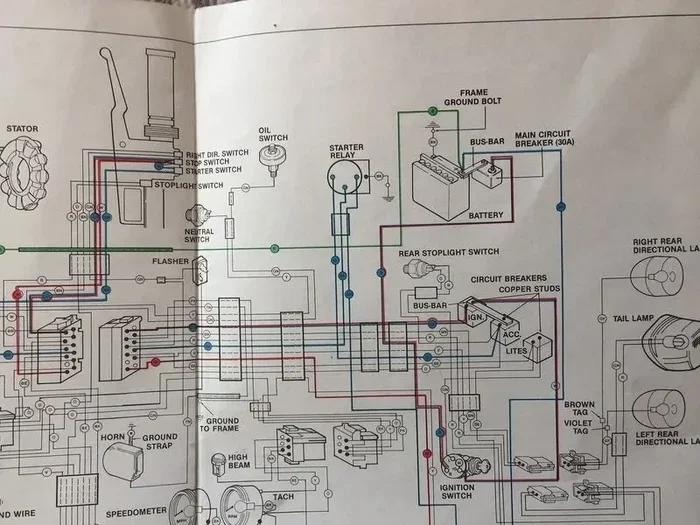
A wiring diagram is a visual picture of your motorcycle’s electrical system. It uses lines, symbols, and labels to show how parts connect. Think of it as a roadmap for electricity. The diagram shows the battery, fuses, relays, switches, and loads like lights and horns. Each line represents a wire, and each symbol represents a component.
You do not need to be an electrician to read one. The diagram uses a standard language. Once you learn a few basic shapes, the rest becomes clear. The goal is to help you follow the path of power from the battery to each device.
Why Every Rider Should Learn to Read One
Knowing how to read a diagram saves you time and money. You won’t have to wait for a mechanic to find a simple fault. You can diagnose problems yourself, even on the side of the road. It also helps when you want to add accessories like extra lights or a stereo.
A clear understanding of your Harley’s wiring makes upgrades safer and easier. You’ll avoid guessing and prevent mistakes. This skill is especially useful for vintage models where factory support may be limited.
Symbols and Colors in Harley-Davidson Wiring Diagrams
Common Electrical Symbols You’ll See
Harley-Davidson wiring diagrams use standard symbols. A circle with a “B” stands for the battery. A zigzag line represents a resistor. A switch looks like a broken line that can connect. A ground symbol is a triangle pointing down. You’ll also see a fuse box drawn as a rectangle with a line through it.
Relays appear as a coil with a switch. The horn relay, starter relay, and voltage regulator each have their own symbol. Learning these basic shapes makes the diagram readable. Most diagrams include a legend that explains every symbol used.
The Meaning of Wire Colors
Wire colors are not random. They tell you what function the wire serves. In most Harley-Davidson models, red wires carry constant power from the battery. Black wires are usually grounds. Yellow wires often go to the headlights. Green wires are for turn signals. Blue wires may control the horn or starter.
The Harley-Davidson wiring color code is consistent across many models. Always check your specific year’s diagram, as changes can happen. For example, a 2010 model might use a different color for the ignition circuit than a 2020 model. The color code helps you trace wires quickly without guessing.
Major Components and How They Connect
Battery, Grounds, and Power Distribution
The battery is the source of all power. It connects to the main fuse box through a heavy red wire. From the fuse box, power flows to various circuits. A ground wire connects the battery’s negative terminal to the frame. This ground path completes the circuit. Without a solid ground, your electrical system will misbehave.
The ground wire is often black or brown. It attaches to the engine and frame with a bolt. A loose ground connection causes many electrical gremlins. Always check the ground first when a light flickers or a accessory stops working.
Ignition Switch and Starter Circuit
The ignition switch controls power to the entire bike. When you turn the key, it sends power to the ignition coil and starter relay. The starter relay then engages the starter motor. A wiring diagram shows this path clearly. You’ll see the ignition switch symbol, then a line to the relay coil.
The relay’s output goes to the starter solenoid. This circuit includes a safety neutral switch that prevents starting in gear. If your bike won’t start, the diagram helps you trace each part of this chain. You can test the switch, relay, and solenoid one by one.
Lighting and Signal Circuits
Headlights, taillights, and turn signals each have their own circuit. The headlight wiring runs from the fuse box through a relay or dimmer switch. The turn signal circuit uses a flasher relay. A wiring diagram shows how the flasher connects to the turn signal switch. The switch routes power to the left or right bulb.
The horn relay works similarly. Pressing the horn button completes the circuit to the horn. The voltage regulator keeps the charging system at the right voltage. It sits between the alternator and the battery. A diagram helps you see how all these parts fit together.
Troubleshooting with Wiring Diagrams
Finding the Source of Electrical Problems
When a light doesn’t work, the diagram helps you trace the path. Start at the power source—the battery. Follow the wire to the fuse. Check the fuse first. If the fuse is good, follow the wire to the switch. Then to the relay, and finally to the load (the bulb or motor). If the wire is broken or a connector is loose, you’ll find the break.
The diagram shows every connection point. You can use a multimeter to test for voltage at each spot. This method turns a confusing problem into a simple hunt. You will find the fault faster than by guessing.
A Simple Step-by-Step Diagnostic Process
- Identify the problem: Is it a light, horn, or starter issue?
- Locate the circuit on the diagram: Find the relevant wires and components.
- Check the fuse: A blown fuse is the most common cause.
- Test for power: Use a multimeter to check voltage at the fuse box.
- Trace the ground: A bad ground causes many electrical gremlins.
- Inspect connectors: Corrosion or loose pins break circuits.
- Repair or replace: Fix the broken wire or faulty component.
Quick Tips and Common Mistakes
Quick Tips for Safe Wiring Work
- Always disconnect the battery negative terminal first.
- Use the correct wire gauge for each circuit. Headlight circuits need thicker wire than signal lights.
- Apply dielectric grease to connectors to prevent corrosion.
- Label any new wires you add. This helps future troubleshooting.
- Take photos before disconnecting anything. You’ll have a reference if you forget.
Common Mistakes That Can Damage Your Electrical System
Skipping the ground connection is a big mistake. A missing ground wire can cause short circuits. Using the wrong wire gauge can lead to overheating. Thin wires in high-current circuits melt and cause fires.
Never splice wires without using proper connectors. Electrical tape alone is not enough. Another mistake is ignoring the fuse box. Fuses protect your wiring. Removing a fuse to “test” a circuit can damage components. Always replace a blown fuse with the correct amperage.
Expert Insights on Harley-Davidson Wiring
Experienced mechanics always double-check the ground path. They also use a wiring diagram to confirm wire colors before cutting. A common tip is to clean connector pins with electrical contact cleaner. This small step prevents many intermittent faults. Remember, the wiring diagram is your best friend when the electrical system acts up.
Where to Find Official Harley-Davidson Wiring Diagrams
Using the Service Manual
Every Harley-Davidson comes with a service manual. The manual contains the full wiring diagram for your model year. It’s the most accurate source. You can buy a printed manual or a PDF. The PDF version is easy to search. Look for the “Wiring Diagrams” section.
The manual also lists wire colors, connector pinouts, and fuse ratings. It gives you the complete picture of the electrical system. If you own a used bike without a manual, you can order one from Harley-Davidson or a dealer.
Online Resources and Aftermarket Guides
Many websites offer Harley-Davidson wiring diagram PDFs. Some are free; others are paid. Be careful with aftermarket diagrams. They may not match your exact model.
Always cross-check with the official service manual. Trusted sites include Harley-Davidson’s own parts catalog and forums like Harley-Davidson Forums. A comparison table helps you choose the right source.
| Source | Accuracy | Cost | Ease of Use |
|---|---|---|---|
| Factory Service Manual (PDF) | 100% accurate for your model | Paid (or free with purchase) | High—searchable and detailed |
| Aftermarket Wiring Diagram Books | Good for general models | Low to moderate | Medium—printed, less searchable |
| Online Forums and User-Shared Diagrams | Varies—may be incomplete | Free | Low—often hard to read |
| Harley-Davidson Dealership Software | Most accurate | Expensive (requires subscription) | High—professional tool |
Key Takeaways
- Wiring diagrams are maps: They show every connection in your Harley’s electrical system.
- Colors and symbols matter: Each wire color and symbol has a specific meaning you must learn.
- Troubleshooting becomes easy: A diagram helps you find faults fast, saving time and money.
- Official sources are best: Use factory service manuals or trusted online resources for accurate diagrams.
- Safety first: Always disconnect the battery before working on any wiring.
- Common mistakes are avoidable: Skipping grounding or using wrong wire gauge can cause fires.
Harley-Davidson Wiring Diagrams Explained gives you the power to understand and fix your bike’s electrical system. You now know how to read symbols, follow wire colors, and trace circuits. With a wiring diagram in hand, no electrical problem is too scary.
Start with small fixes like replacing a fuse or a headlight bulb. As you gain confidence, you can tackle bigger projects like adding accessories or rewiring a vintage model. Keep your service manual handy, and always prioritize safety. Your Harley will reward you with years of reliable rides.
Frequently Asked Questions
What does a Harley-Davidson wiring diagram show?
A wiring diagram shows how every electrical component connects. It maps the battery, fuses, switches, relays, and loads like lights and horns. The diagram uses lines for wires and symbols for parts.
How do I read Harley-Davidson wire colors?
Red wires usually carry constant power from the battery. Black wires are grounds. Yellow wires often go to headlights. Green wires are for turn signals. Blue wires may control the horn or starter. Check your specific manual for exact colors.
Can I use an aftermarket wiring diagram safely?
Yes, but be careful. Aftermarket diagrams may not match your exact model year. Always cross-check with the official Harley-Davidson service manual. Use aftermarket guides as a supplement, not a replacement.
What tools do I need to troubleshoot with a wiring diagram?
You need a multimeter to test voltage and continuity. A basic set of wrenches, screwdrivers, and wire strippers helps. Dielectric grease protects connectors. A flashlight and a notepad to label wires are also useful.
Why does my Harley have electrical shorts?
Shorts often happen when a wire’s insulation wears out. A bare wire touches the frame or another wire. Bad grounds can also cause shorts. A wiring diagram helps you trace the damaged wire and repair it properly.
Where can I find a free Harley-Davidson wiring diagram PDF?
Some forums and owner sites offer free PDFs. However, these may be incomplete or for a different model year. The safest free option is the Harley-Davidson owner’s manual, which often includes a basic diagram. For full details, buy the official service manual.